
Technology
System Design of the
Multi-U-Tube Probe
The design principle and the reproducible, fixed positioning of heat exchangers in the borehole form the technical foundation for the demonstrably highly efficient heat output.
Geometric Design Principle
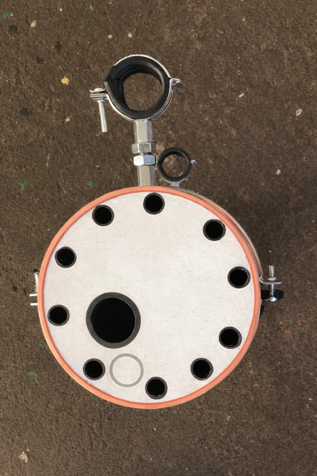
The Multi-U-Tube Probe (MU probe) consists of a central pipe concentrically surrounded by 10 outer pipes in the annular space. Water and brine circulate in the Multi-U-tube circuit.
This principle creates a 30–35 % larger heat transfer surface compared to the conventional double-U-tube probe within identical borehole geometry.
The same enlarged contact surface works in both directions: in winter the probe extracts more heat — in summer it returns excess heat to the ground more efficiently. This regeneration capability is critical for probe fields in densely built-up areas, as it prevents long-term cooling of the subsurface.
100-year simulation
The 100-year simulation (GeoTherm 2026) confirms: at approximately 92 % regeneration, a cooling capacity of 287 kW in the Multi-U-tube probe field compared to 220 kW when using double-U-tube probes.
Cross-section · MU probe
Schematic
Execution
Technical Specifications
| Parameter | MU probe | Double-U (reference) |
|---|---|---|
| Borehole diameter | approx. 150 mm | approx. 150 mm |
| Probe foot | 94 mm | 90–95 mm |
| Number of pipes | 1 central + 10 outer | 2 × 2 pipes |
| Material | PE100 / PE100 RC | PE100 / PE100 RC |
| Heat transfer surface | +30–35 % (vs. ref.) | Reference |
| Heat extraction (possible) | +25–50 % possible | Reference |
| Heat extraction (measured) | +36 % | Reference |
| Grouting thermal cond. (rec.) | 1.4 W/(mK): Standard grouting | 2.4 W/(mK): Enhanced grouting |
| Grouting | Contractor method, bottom to top | Likewise |
| Hydraulics | Compatible with standard heat pumps | Likewise |
System Details
Material & Manufacturing
- Probe head and foot: PE100
- Pipes (central and outer): PE100 RC
- Complete manufacturing with factory-welded connections
Hydraulics
- Pressure loss sufficient for standard HP applications
- Flow rate designed for common brine-water heat pumps
- Applied and tested in reference projects
Installation & Grouting
- Thermally enhanced suspension grouting is not required
- System permeabilities of MU analogous to those of DU
- Grout sleeve integrates the advantages of geothermal socks
Scalability
- Probe length in 10 m increments up to 150 m
- Particularly suitable for large systems
100-year simulation · GeoTherm 2026
Simulation Framework
The following values originate from a 100-year simulation of a 25×4 probe field (GeoTherm 2026, BLZ Geotechnik / TU Freiberg / Transflow).
Calculated with ModThermWg (Transflow GmbH) — a numerical finite-difference simulation, not a heuristic approximation. Standard BHE planning tools do not support the MU probe. Transflow partnership and simulation services →
Subsurface
Operation
Results: 4-Scenario Comparison
| Parameter | DU w/o regen. | DU with regen. | MU w/o regen. | MU with regen. |
|---|---|---|---|---|
| Heating capacity (kW) | 193.1 | 190.1 | 260.1 | 257.2 |
| Cooling capacity (kW) | — | 220.9 | — | 287.7 |
| Heat output (MWh/a) | 463.4 | 507.1 | 624.3 | 673.3 |
| Cooling output (MWh/a) | — | 305.0 | — | 397.5 |
| HP electricity consumption (MWh/a) | 108.7 | 114.2 | 146.8 | 153.6 |
| SCOP heating | 4.27 | 4.16 | 4.25 | 4.14 |
| SCOP heating + cooling | — | 7.03 | — | 7.20 |
| Regen. efficiency (%) | — | 92.0 | — | 91.9 |
Simulation: 25×4 probe field, 100-year run. Source: GeoTherm 2026, BLZ Geotechnik / TU Freiberg / Transflow.
Documentation
Technical Documentation
Measurement data sets and detailed specifications available on request.
Request documentation